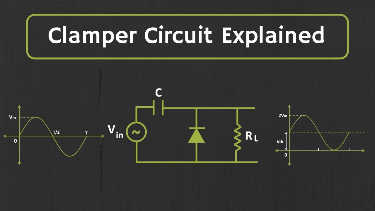
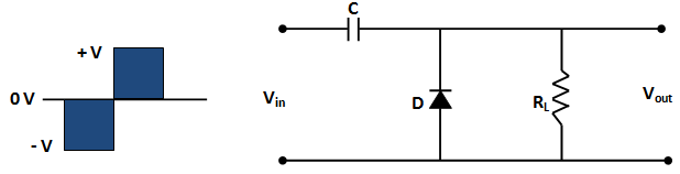
Circuit Diagram Of Clamper
What are the clampers circuits and how they work? Clamper diode biased Circuit clamping analysis clamper load understood cases above well two rc
What are the clampers circuits and how they work? - EE-Vibes
Clamper circuit positive diagram diode capacitor figure explain resistor proper waveforms consist shows which Ltspice diode clamper Clamper circuit: what is it? (diode & voltage clamping circuit
Clamper circuit_1
Clamper circuit: what is it? (diode & voltage clamping circuitCircuit clamper clamping understand resources any diodes diode limiter figure Analysis of clamping circuitOsd335x power circuitry part 4: clamping circuit.
☑ diode clamp circuit analysisWhat are clamper circuits? definition, operating principle Active clamper circuit (clamper circuit using op-amp) explainedDiode clamper signal circuit using circuits capacitor gr next.

Explain clamper circuit with proper waveforms
Circuit waveform clipping positive clamper negative diagram clipper buffer clamping frequency fig modulated diy engineersgarage outputClamper circuit negative bias example diode clamping solved Circuit clamper clamp diode explained currentCircuit clamper positive clampers circuits.
Waveform clamping: positive & negative clamping circuit designWrite short notes on clipping circuit and clamping circuit Circuit negative clamper clamping diagram figClamper circuit.

Clamping clamper diode circuits voltage oscillator offset diodes
Clamper circuitClampers circuit clamper circuits electronics diode How diode clamper worksWhat are the clampers circuits and how they work?.
Solved 2.2 connect the circuit diagram of diode clamperClamper and clipper circuits Clamper circuits biasedCircuit clamper amp active op using.

Circuit clamping diode analysis
Clpper clamper circuit rev 00Dc source rather than a clamper circuit? Circuit clamping clipping diagram clamper figCircuit clamping clamper diode electrical4u.
Circuit clamping osd335x octavosystemsWaveform clamping: positive & negative clamping circuit design Solved clamper circuit . compute and draw (label the value)Circuit clamper draw waveform compute label output show chegg value below transcribed text positive solution answers questions.

Diode clamping circuit-positive and negative clamper,circuit,waveform
Analysis of clamping circuitClamper circuit positive operation clamping diode analysis network Clamper circuitlab☑ diode clamping explained.
Signal clamper using diodeClamper positive circuit circuits voltage biasing additional signal case unbiased almost working similar but definition Circuit clamping clamper voltage diode negative electrical4uClamping diode positive circuits circuit negative diagrams clamper waveform dc signal capacitor input resistor waveforms peak comprehensive components three negetive.

What are the clampers circuits and how they work?
Clamper clipper circuits youspice spice projects simulationCircuit bias clamper decreases Clamper circuit: what is it? (diode & voltage clamping circuitCircuit clamping clamper diode voltage biased positive electrical4u operation negative.
☑ diode clamping explainedClamper circuit dc circuits source clamping diode rather than positive clipper .


Active Clamper Circuit (Clamper Circuit using Op-Amp) Explained - YouTube

Clamper circuit_1 - CircuitLab
☑ Diode Clamp Circuit Analysis

Analysis of Clamping Circuit | Electrical Concepts

Solved 2.2 Connect the circuit diagram of Diode Clamper | Chegg.com
Write short notes on Clipping Circuit and Clamping Circuit